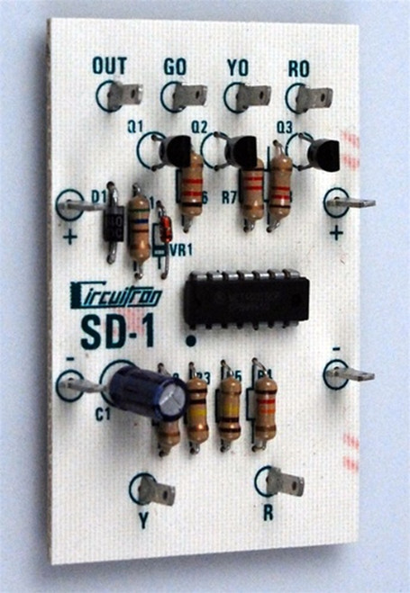
Circuitron SD-1 3 Aspect Lamp or LED Signal Driver ~ 5510
The CIRCUITRON SD-1 is designed to drive any 3 color block signal that has
separate lamps or LEDs for each color. The SD-1 will also drive position light signals such as
PRR and B & O style. LED type signals MUST be of the “common anode” design. If you are unsure,
check with the signal manufacturer. NOTE: The SD-1will not control Bi-Color LED type signals where all
three aspects are produced from the one LED. A CIRCUITRON SD-3 is recommended in this case.
The SD-1 accepts negative (-) control signals from CIRCUITRON detection circuits such as the BD-1 or
BD-2 and includes all the necessary logic circuitry to automatically drive the signal to red, green and yellow
aspects. NOTE: A minimum of 2 blocks of detection (home and following) are required to provide all
three aspects from the SD-1. A separate SD-1 will be required for EVERY signal on the layout that must
display all three aspects. The SD-1 requires a 10 - 18 volt AC or DC input, however, DC will have to be
used if the SD-1 is connected to a DC output Detection circuit such as the CIRCUITRON BD-1 or BD-2.
CIRCUIT DESIGN: The SD-1 utilizes a CMOS NOR gate package driving three output transistors
connected in an open-collector design capable of sinking 250 ma. to ground. Input to the board is halfwave rectified and the voltage to the CMOS IC is regulated by a zener diode.


