Circuitron BR-1 Bell Ringer Circuit With Bell ~ 5700
The CIRCUITRON BR-1 and BR-2 Bell Ringer Circuits are identical
electronically. The BR-1 includes the mechanical bell while the BR-2 requires the modeler to supply
the bell. Any standard electromagnetic type doorbell may be used. The circuit provides adjustable
ring rate and strike force (volume). The BR-1 and BR-2 require a 12-18 volt AC or DC input for
proper operation. A control terminal is provided on the circuit board for easy connection to any
CIRCUITRON detection unit. Manual control through the use of a pushbutton or toggle switch is also
easily achieved for use in simulating locomotive bells. The use of a true mechanical bell results in a
much more realistic sound than can be achieved using all-electronic bell simulator circuits.
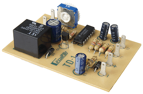
CIRCUIT DESIGN: The BR-1 and BR-2 Bell Ringer Circuits use a combination of state of the art
electronics and a traditional electric doorbell to achieve a realistic bell sound. The circuit board
contains an on-board rectifier section to allow operation from AC or DC sources. The electronics
consist of a low-power CMOS integrated circuit configured as a pulse generator. The pulse width is
fixed, but the time between pulses is adjustable. The output pulses drive a darlington output
transistor connected as an emitter follower which provides the current gain necessary to power the
bell. Power for these high current pulses is stored in the large 2200 mfd. capacitor which is charged
through an IC voltage regulator. The IC provides isolation from the input source and at the same
time provides a quick recharge of the capacitor after each pulse. The Control terminal gates the
pulses through the CMOS logic when it is connected to ground (-).
INSTRUCTIONS: The CIRCUITRON BR-1 and BR-2 circuits can be connected with .110" solderless
connectors or by soldering leads directly to the terminals on the printed circuit board. If soldering,
use a small pencil-type iron and electronics-grade, rosin core 60/40 solder (available at Radio Shack).
Use only as much heat as necessary to obtain a good joint and do not wiggle the terminal until the
solder has cooled completely.
MOUNTING AND MODIFYING THE BELL: A couple of simple modifications to the bell supplied
with the BR-1 are necessary to ensure the best possible sound. Similar modifications can be made
on most doorbells if you have a BR-2 and are supplying your own bell.
1) Remove the cover from the bell by squeezing in at the top and bottom of the cover.
2) If you will refer to the drawing on the next page, you will note that there is a terminal strip next
to the striker arm. This terminal strip contains two connection points. One of these will have a
screw threaded into it. The other connection pad may or may not have a hole in it. If there is a
hole, remove the screw that is threaded directly into the metal frame of the bell and thread it into
the hole in the terminal. If the second terminal does not have a hole, you will have to solder a
wire directly to the terminal pad or mechanically attach a wire to the vertical portion of the pad
by twisting it tightly around the terminal. The connections from the circuit board will be made to
these two points and will thus connect the circuit directly to the coils on the bell. If this
modification is not performed, current to the coils will flow through the breaker points and may
result in multiple rings per strike which will give an unnatural sound.
3) A small block of foamed plastic should be cut from the packing material supplied with the BR-1 or
BR-2 and cemented to the metal frame of the bell so that it just lightly contacts the clapper arm
(see diagram). The foam helps to dampen vibration of the arm which results in a clearer ring.
4) Mount the bell under the layout in the vicinity of the crossing. If you prefer, the bell can be
contained within a suitable structure close to the crossing. DO NOT mount the bell directly to a
hard surface. An annoying knock may result. We recommend you mount the bell onto a block of
foamed plastic using contact cement such as Walther’s GOO. An alternate means of mounting
the bell is to suspend it under the layout by its own wires. Either method should prove effective
in preventing the strike sound from being transmitted throughout the layout.
WIRING THE CIRCUIT: Mount the BR-1 circuit board in a convenient location. You may drill small
holes in the corner pads of the circuit and use screws and standoffs, or use a section of
CIRCUITRON’S Printed Circuit Mounting Track (PCMT) for easy snap-in mounting of the circuit board.
All wiring of the Bell Ringers can be made using light gauge (22-24 ga.), preferably stranded wire.
1) Connect two wires to the terminals on the circuit board labeled . Run these wires to the
bell and connect them to the coil terminals as described above and shown in the diagram.
2) For automatic operation of the BR-1 or BR-2, connect a wire from the Control Terminal on
the circuit board to the Output Terminal of any CIRCUITRON Detection Unit. For manual
operation, connect a pushbutton or switch between the Control Terminal and the LEFT
Terminal as you view the circuit board from above.
3) Connect the terminals to a 12 - 18 volt AC or DC source. If you are using the BR-1 or
BR-2 with a detection circuit, then you MUST use a DC power source. If possible, use the
same supply for both the detection circuit and the bell ringer. If you must use different power
sources, make certain they are both DC supplies and that the ground connections on both
power supplies are connected together.


