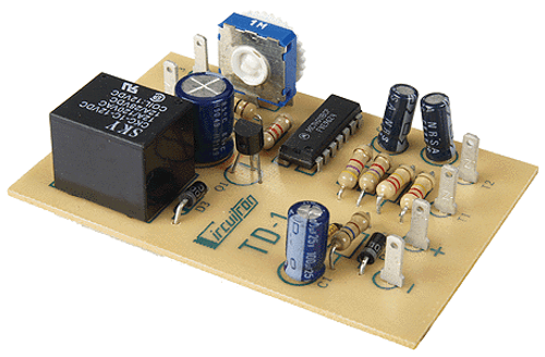
Circuitron AR-1 Automatic Reversing Circuit ~ 5400
The CIRCUITRON AR-1 is an automatic polarity reverser that is ideally suited for use
with point to point layouts, displays, test tracks or reverse loop setups. The AR-1 can safely switch up to 6
amp loads, making it compatible with virtually all scales. The AR-1 uses tiny Opto-Sensors mounted between
the rails where they are shaded from ambient room light by a piece of rolling stock. The AR-1 requires a
filtered 12 volt DC supply for proper operation. Pushbuttons may be incorporated into the circuit for manual
reversing.
INSTRUCTIONS: Please refer to the diagrams for labeling and Opto-Sensor locations. The CIRCUITRON AR-1
can be connected with .110” solderless connectors or by soldering leads directly to the terminals on the
printed circuit board.
1] Mount the AR-1 in a convenient location. A section of CIRCUITRON’s Printed Circuit Mounting Track
makes this step simple.
2] Install Opto-Sensors at the points you wish to have the polarity reverse following the instructions packed
with them.
3] Connect one lead from each of the Opto-Sensors together with light gauge (22-24 ga.) wire, and run that
wire to the Sensor Drive Terminal on the board.
4] Run individual wires from the remaining leads of the two Opto-Sensors to the terminals marked and
on the printed circuit board.
5] If it is desired to have more than one reversing point per side, such as on a siding or spur track, additional
Opto-Sensors may be connected in series up to a maximum of three (3) per side total. (See Figure 2)
6] Connect wires from the terminals at the top of the AR-1 to the track as shown.
7] Connect the terminals to the variable DC output of a throttle or power pack (Track Power).
8] If manual reversing capability is desired, connect a momentary pushbutton between and the supply
terminal as shown. Do the same with and the supply terminal.
9] Connect the and supply terminals to a FILTERED 12 volt DC power supply. The AR-1 may be
powered from the DC accessory terminals on a power pack, but the voltage should be checked with a
voltmeter to be certain that it does not exceed 14 volts DC. WARNING: Excessive voltage may cause relay
damage which is not covered by warranty.
10] Making certain that no rolling stock is over either Opto-Sensor and that room lighting is at the level it will
be at during operation, rotate the sensitivity control P1 until indicator lamp L1 is on. Turn the control back
until L1 just turns off. Rotate the control about 10 degrees further to eliminate excess sensitivity. Follow
the same procedure with P2 and L2.
11] Roll a train car over the Opto-Sensors and make certain that the corresponding indicator (L1 or L2) lights
when the Opto-Sensor is covered. If it does not, repeat step 10.
12] Place a train on the track and adjust the throttle for the desired speed. If the train does not reverse when it
covers one of the Opto-Sensors, reverse the throttle direction or interchange the connections to the track.


